|
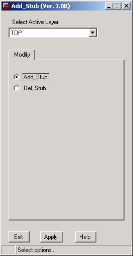
AAdd Stub
Marks the exact length along a cline by adding
a temporary via at a user specified distance.
The designer can then change the trace width
independently on either side of the temporary
breakpoint.
• Extremely useful when RamBus Routing is
required.
• Automatically places multiple vias on
terminations that
have multiple clines
connecting to it.
|
|
|
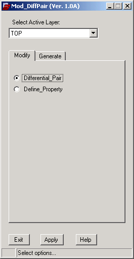
AMod DiffPair
Automatically create sets of differential pairs
by keying on the net names.
• Currently four possible naming conventions
can be selected.
|
|
|
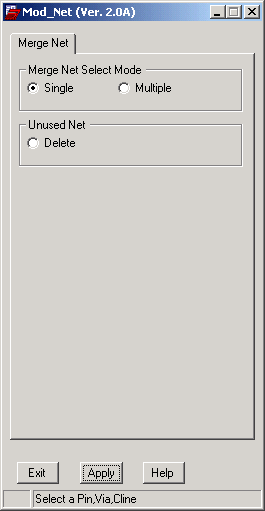
AMod Net
Interactively add and or merge new nets to
existing vias, clines and pins.
• Use the multiple option to select groups of
vias, tracks and
pins to merge to the new net.
• Find and delete unused nets .
|
|
|
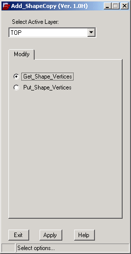
AAdd ShapeCopy
Copy complex shapes from one design to
another.
• Select the target shape and the software
creates a shape file to disk.
• Read the shape file back into any design,
recreating the shape exactly like
the original.
|
|

|
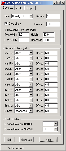
AGen Silkscreen
A replacement for the "Auto Silk" layers.
Intelligently creates a silkscreen layer
using
parameters you specify by component type.
• Generate silkscreen interactively for one
component at a time.
• Choose to generate for only the resistors
on bottom side, removing
the clutter of
chips capacitors.
• Automatically creates the correct size text
block to achieve true
and accurate
finished text size.
• Interactively add "plus" and "Diode"
shapes to components
missing these
outlines.
• Verify silkscreen clearance to vias and
pads or to solder
mask openings.
• Report on missing silkscreen text,
overlapping text
and text under
components.
|
|
|
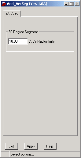
AAdd ArcSeg
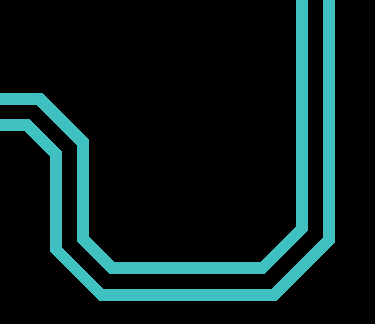
This program converts 90 and 45 degree
routing into arced segments.
• Automatically detects differential
pairs when one trace is selected.
• Control the Arc radius.
• Works with metric an imperial designs.
|
|
Before
|
After
|
|

|
|
|
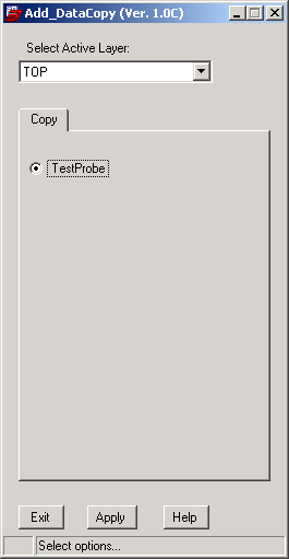
AAdd DataCopy
Copy the testpoints from any design to your
current board.
• Program determines if a suitable location
exists (a via or pin must be present),
and no
pre-existing testpoint is present at the
location.
• Use the same bed of nails fixture for multiple
designs.
|
|
|
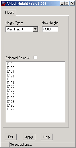
AMod Height
Modify the minimum component height or maximum component height values, to
one or multiple components, in a single pass.
• Select target components by refdes, symbol
type
or component type.
• Saves time compared to fixing the database,
or changing the values
one at a time.
|
|

|
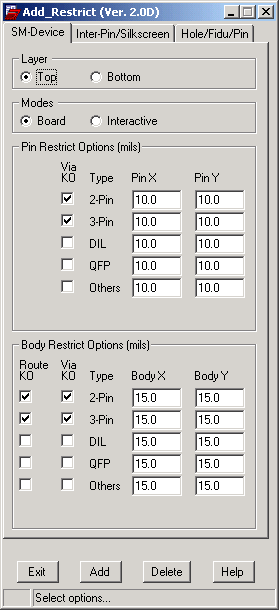
AAdd Restrict
Re-Named to AAdd KeepOut
Add Route and Via keep-outs automatically and interactively to components, pins, vias,
fiducials, text, lines, shapes (logos) and holes. Keeps Specctra from placing tracks or vias where you don't want them.
• Add user defined Route and Via Keep -
outs to components bodies and pins
automatically.
• Add Via Keep-outs to silkscreen lines
and text, before auto-routing.
• Add Route keep-outs between the pins
of DIL and QFP devices .
• Interactively add circular, square or
rectangular Route and Via Keep-outs
to any hole or pin.
• Components can be in any angle of
rotation.
• Works in all units of measure.
(metric/imperial)
• Reduces board clean-up time. Let
Specctra figure out the via's placement.
|
|
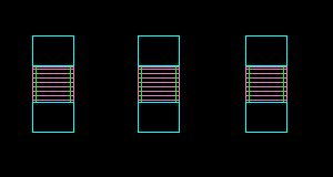
Keep-outs added to device bodies.
|
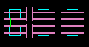
Via Keep-outs added to device pins.
|
|
|
|
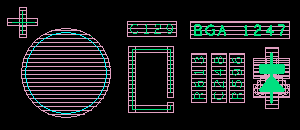
Via Keep-outs added to lines and text.
|
|
|
Route Keep-outs added between the pins of DIL and QFP devices.
|

|
|
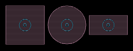
Route and/or Via Keep-outs added to any hole, fiducial or pin.
|
|
|
AMod_Object
This program behaves almost like the UniCAD layout tools. When users select a symbol, a pin, a via, a copper
track or a text; all the programs related to the selected object are available at the right mouse button.
1. If a Symbol is selected, user can "Move" it to a new location with the "Left-Mouse". Other features user can select on the "Right-Mouse" are:
- Move By Offset.
- Move By User Entry.
- Delete (i.e. Unplace symbol).
- Rotate (i.e. 90 degree increment).
- Relayer (i.e. Mirror symbol to other layer).
- Lock/Unlock.
- Query Pins.
2. If a Pin is selected, user can "Route" a track with the "Left-Mouse". Other features user can select on the "Right-Mouse" are:
- Route/Unroute.
- Lock/Unlock.
- Net Merge.
- Test Probe (i.e.Probe Add, Probe Delete, Probe Lock, Probe Unlock, Select Probe Layer).
- Query Pad Stack.
- Change Pad Stack.
3. If a Via is selected, user can "Route" a track with the "Left-Mouse". Other features user can select on the "Right-Mouse" are:
- Route/Unroute.
- Lock/Unlock.
- Net Merge.
- Delete.
- Test Probe (i.e.Probe Add, Probe Delete, Probe Lock, Probe Unlock, Select Probe Layer).
- Query Pad Stack.
- Change Pad Stack.
4. If a copper-track is selected, user can "Route" a track with the "Left-Mouse". Other features user can select on the "Right-Mouse" are:
- Relayer (i.e. Relocate track to other layer and vias are added on both ends).
- Route/Unroute.
- Lock/Unlock.
- Net Merge.
- Delete (i.e. Only delete a segment).
- Test Probe (i.e. A "virtual" probe can be added to the track).
- Query.
- Change Seg Width.
5. If a text is selected, user can "Move" it with the "Left-Mouse". Other features user can select on the "Right-Mouse" are:
- Delete.
- Rotate.
- Text2Symbol (i.e. This will link a text to a symbol).
- ChangeText.
- Change Width
|
AMod_Shape
This program allows users to modify the symbol shapes on layer "PACKAGE GEOMETRY/PLACE_BOUND_" to a new symbol shapes
on layer "PACKAGE GEOMETRY/ASSEMBLY_".
|
AMod_Signal --> ReNamed to AMod_Net
This program allows users to merge new NETS to selected PINS, VIAS or CLINES.
If the net is not yet defined, the program will define a new one then proceed to merge the net. Also, users can
query the unused nets and remove them.
|


